Crossover Design for DIY Speakers: A Measured Approach
The crossover is where a DIY speaker is won or lost. It splits the signal between woofer and tweeter, and a good one makes two drivers behave like a single coherent source while a bad one leaves a dip at the crossover frequency, a forward presence region, or smeared imaging. The hard truth most beginners learn late: textbook crossover values calculated from a driver’s nominal impedance almost never measure flat, because real drivers are not flat resistive loads. The only reliable path is to design the filter to the drivers’ measured response in your actual cabinet.
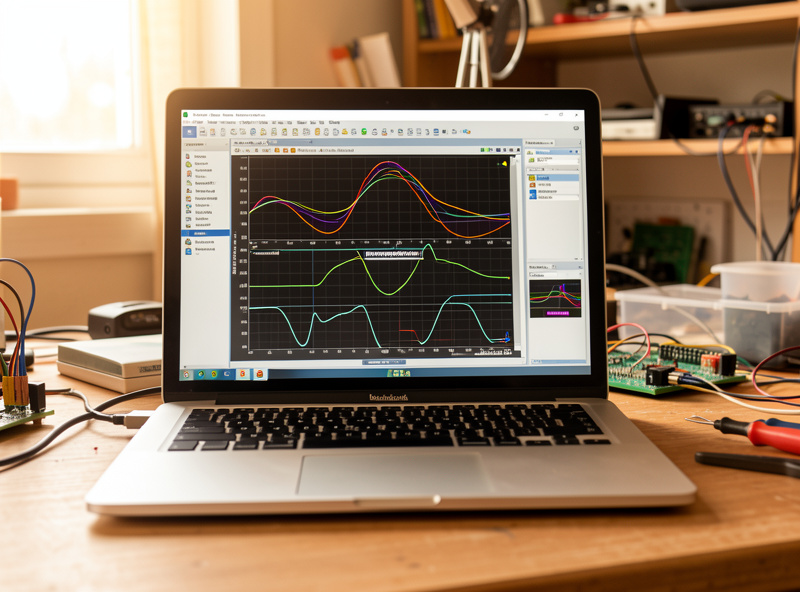
This is the part of speaker building that rewards the measurement-first discipline I bring to everything in my listening room. You cannot hear a 3 dB crossover-region dip as “a dip” — you hear it as a vaguely recessed, lifeless speaker and you blame the wrong thing. A sweep shows you exactly what’s happening. This guide walks the real workflow: what a crossover does, why calculators mislead, how to design to measurements, and where component quality actually matters. For the whole project, start at the DIY speaker building guide; this is the deep dive on its hardest step.
What a Crossover Actually Does
A passive crossover is a network of inductors, capacitors, and resistors that routes low frequencies to the woofer and high frequencies to the tweeter, with the two handing off at the crossover frequency. Two things define it: the crossover frequency (where the handoff happens) and the slope or order (how steeply each driver rolls off past that point). A first-order filter rolls off at 6 dB per octave; second-order at 12 dB; fourth-order at 24 dB. Higher orders keep each driver in its comfort zone but use more components and shift phase more.
The crossover also has to do three jobs beyond simple filtering, and these are what the calculators ignore. It must compensate for baffle step — the roughly 6 dB relative loss in the lower frequencies that wrap around a real cabinet. It must flatten the driver impedance where needed (a Zobel network on the woofer, sometimes an impedance-correction network on the tweeter) so the filter behaves as designed. And it must pad the more sensitive driver down so the two levels match. Skip baffle-step compensation and you get the classic thin, bright first build.
Why Online Crossover Calculators Fail
Plug 8 ohms and a 2.5 kHz target into a crossover calculator and it spits out tidy inductor and capacitor values. Build that filter and it will almost certainly measure nothing like flat. The reason is simple: the calculator assumed your drivers present a constant 8-ohm resistive load, and they do not. A woofer’s impedance rises with frequency because of its voice-coil inductance; a tweeter’s impedance peaks sharply at its resonance. The filter interacts with that real, swinging impedance, so the actual acoustic roll-off lands somewhere other than the textbook curve.
| Filter order | Slope | Components per driver | Trade-off |
|---|---|---|---|
| First-order | 6 dB/octave | 1 (one coil or one cap) | Simple, phase-coherent in theory, but drivers overlap a lot — demands very well-behaved drivers |
| Second-order | 12 dB/octave | 2 | The practical workhorse; good control, manageable parts count |
| Third-order | 18 dB/octave | 3 | Tighter driver protection, more phase rotation |
| Fourth-order (LR4) | 24 dB/octave | 4 | Excellent driver isolation and a clean acoustic sum; the most parts and design care |
Note that the electrical order you build and the acoustic order you actually get are different things, because the driver’s own natural roll-off adds to the filter’s. A driver rolling off naturally plus a second-order electrical filter can sum to a fourth-order acoustic slope. This is exactly why you design to measurements, not to a target on paper — the acoustic result is what reaches your ears.
The Right Workflow: Measure, Simulate, Verify
Here is the process that actually produces a flat speaker. First, measure each driver mounted in the finished cabinet — a gated quasi-anechoic frequency response and an impedance measurement for each, taken on your design axis. This captures the baffle diffraction and baffle step that no data sheet includes. If you’re new to taking these measurements, my REW measurement guide covers the calibrated-mic setup; the driver-measurement basics also tie back to the driver selection guide.
Second, import those measurements into a free crossover simulator like VituixCAD, and design the filter to produce a flat summed response on-axis with a clean phase transition through the crossover region. You adjust component values in software and watch the summed curve in real time — this is where you add baffle-step compensation and tame any driver break-up with a notch filter. Third, build the filter you designed, install it, and re-measure the finished speaker to verify the simulation matched reality. When my crossover region measures ±2 dB through the handoff, I know it’ll image properly; that’s the payoff for doing it in the right order.
Component Quality: Where It Matters and Where It Doesn’t
This is another zone thick with audiophile mythology, so the measurement-informed version: topology done right matters enormously, exotic component branding much less. That said, a few component choices have real, measurable consequences. Use air-core inductors in the tweeter’s signal path rather than iron-core, because iron-core coils can saturate and add distortion at higher levels; a series resistance difference between coils also shifts your filter, so the inductor’s DC resistance is a parameter, not a detail. For capacitors, a decent polypropylene film cap in the tweeter circuit is the sensible standard.
Where the money does not buy measurable improvement is boutique “audiophile” capacitors costing ten times a good film cap, sold on adjectives rather than data. I’ve compared the claims against measurements and the differences live in the noise — the same skepticism I apply to cables, which I unpack in do expensive audio cables make a difference. Spend your budget on getting the design right and on solid air-core inductors and film caps; don’t spend it on jewelry. A search for crossover inductors and film capacitors covers the parts a typical two-way needs.
If You’d Rather Not Design One
Designing a crossover from measurements is the most demanding skill in speaker building, and there’s no shame in skipping it for your first project. A proven published design or a kit comes with an already-engineered, tested crossover — you assemble a known-good filter and learn clean layout and soldering without the engineering. That’s the lowest-risk way to get a great-sounding result while you build up to designing your own, and I cover the options in best DIY speaker kits 2026. Either way, the crossover is mounted in the cabinet you built, so do your soldering before final assembly while you still have easy access.
As an Amazon Associate I earn from qualifying purchases.
Frequently Asked Questions
Why do online crossover calculators give wrong values?
Because they assume your drivers present a flat resistive load, which they do not. A woofer’s impedance rises with frequency from voice-coil inductance and a tweeter’s impedance peaks at resonance. The filter interacts with that real swinging impedance, so the actual acoustic roll-off lands somewhere other than the textbook curve. You must design to measured driver response.
What is baffle step compensation and why does it matter?
Baffle step is the roughly 6 dB relative loss in lower frequencies that wrap around a real cabinet versus the highs that stay directional. A crossover must compensate for it, usually with an inductor-and-resistor network on the woofer. Skip it and you get the classic thin, bright, fatiguing first build, because the bass is effectively 6 dB low.
What crossover order should I use for a DIY two-way?
A second-order (12 dB/octave) electrical filter is the practical workhorse for most two-ways – good driver control with a manageable parts count. But the acoustic order you actually get combines the filter with each driver’s natural roll-off, which is why you design to measurements rather than picking an order on paper.
Do expensive crossover capacitors sound better?
Topology done right matters enormously; boutique capacitor branding much less. Use air-core inductors in the tweeter path and a decent polypropylene film capacitor, because those have measurable benefits. Capacitors costing ten times a good film cap are sold on adjectives, not data, and the differences live in the measurement noise.
Can I design a speaker crossover by ear?
Not reliably. A 3 dB dip at the crossover region does not sound like a dip – it sounds like a vaguely recessed, lifeless speaker, so you adjust the wrong thing. A frequency sweep shows exactly what is happening. Design to measurements in a simulator, build the filter, then re-measure to verify.
What software do I use to design a crossover?
VituixCAD is the free standard for designing a passive crossover to measured driver responses, letting you adjust component values and watch the summed on-axis response and phase in real time. You feed it gated frequency-response and impedance measurements of each driver taken in the finished cabinet with a calibrated microphone and REW.